Most folks in the HVAC industry know using Right-Draw® is the fastest way to draw a structure to calculate a load and/or design ducts. Yet it’s not uncommon for MiTek-Wrightsoft employees to hear from new and existing customers how they didn’t know certain features existed – features that really speed up the drawing process.
Why Changing Is Worth the Effort…
Reason #1: Some customers enjoy using Right-Draw® without implementing any new techniques. The software is easy to use, and makes their job faster and more accurate than if they were to do all the calculations by hand. They don’t want to change anything about how they use the software. Usually they have been customers since the 80’s when the software was originally launched.
At MiTek-Wrightsoft, we believe our customers significantly benefit from adapting with our software as we design improvements. When Right-Suite Universal was launched in 1986, we had a hunch it was going to be a game-changer for the HVAC industry. Over the years, our customers have confirmed we were right. But we don’t want to stop there… Our goal is to keep implementing changes to make Wrightsoft’s solutions even better. For example, if we can reduce a task from 5 steps down to just 2 steps – we are going to do it! As technology and our world evolves, our goal is to keep step and to implement changes that will continue to help the HVAC industry work more efficiently and effectively.
Did you take a MiTek-Wrightsoft Training Course 5-15 years ago, and now you find there are many tools you didn’t know existed and don’t know how to use? It might be time to sign up for a new training course. We also offer training videos on YouTube, and wrightsoft.com/university to help you sharpen your skills.
Tracing Is Faster than Drawing – Just Import a DWG or PDF File
Feature #1 and Reason #2: In 2011, Wrightsoft added the ability to import a PDF file (reflecting a home or commercial building’s floorplan) directly into Right-Draw®. Once imported, you will use it as an outline to quickly trace a floorplan as opposed to drawing it by hand. Right-Draw® is fast, but tracing in Right-Draw® is faster. If you inquire, some homeowners will have their home’s blueprints on hand. Why would you want to take the time to run down to FedEx-Kinko’s to have the blueprints scanned into a PDF file? When compared to drawing a floorplan by hand, you will save an enormous amount of time by tracing a home’s dimensions in Right-Draw® instead. The 2 minutes and $2 you think you are wasting on this task will doubtlessly become a worthwhile investment when you start reaping the rewards.
Feature #2: In 2007, Wrightsoft added the ability to import a CAD file (DWG or a DXF) into Right-Draw®. You do not need to own AutoCAD in order to use one of these files in Right-Suite® Universal. Even though we added CAD import to our software over 10 years ago, many are still learning about it for the first time. Customers who have been using RSU for decades are no exception! You can use a CAD file just like a PDF to trace the structure in Right-Draw®, which (not to beat a dead horse here) is faster than drawing from scratch. The biggest advantage to using CAD files over PDF files is that CAD files are already to scale. With a PDF you will have to spend additional time scaling the drawing in the beginning to ensure a 12’ x 12’ room actually equates to 12’ x 12’. If you forget to scale your PDF then you might trace a room that is 12’ x 12’ and have it turn out to be 6’10” x 6’10”. Therefore, CAD is the fastest way to trace.
Taking Communication to the Next Level
One additional benefit to importing a CAD (file versus a PDF) is you can write layers back to the CAD file. Essentially, you will produce the load and duct design, then save the duct design back to the CAD file as a new layer. When you send the file back to the originator, he/she will also be able to see your duct designs. This application takes communication to the next level.
Mike Moreno, Wrightsoft’s National Sales Manager, pointed out to me, “Our world is all about sharing files.” I think this is an insightful statement. In 2007, when this application was implemented, we didn’t even understand how important sharing files would become. Yet, as time goes by, every business is realizing the importance of improved communications.
When you work with builders, architects, and engineers on projects, sharing files is a huge benefit to the entire team. Whether this feature is used for commercial projects or residential new-builds, all the involved parties will be kept in the know to reduce the possibility of interferences and problems down the road. It’s a great tool for reducing mistakes and increasing ROI.
Trust and Sharing Go Hand in Hand
Reason #3: What if an architect or engineer won’t give you a CAD file? Some architects and engineers look at a CAD file as something they sign-off on. If it gets changed by accident, they don’t want to be held accountable for any potential mistakes. Their license is on the line, so they might not feel comfortable giving a CAD file to you or anyone else for that matter. It’s really not personal. Most will give you a PDF if you request it, so don’t hesitate to ask. When you have worked with someone a long time, and built trust with them, then you might find they begin to share CAD files as well.

Need Help Getting Started with the Import Tool?
Short Import Description:
1) Go to the Draw Screen
2) Lock all the floors except the first floor
3) Click on the 1st Floor Building Layer
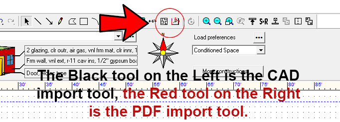
4) Click on the PDF or CAD import tools – they are right next to each other above where it says Load Preferences. See image – inside the red circle I have highlighted the two tools. The black one on the left is the CAD tool and the red one on the right is the PDF tool. When you hover over either of the icons, you will see which is which.
5) Draw a box on the Draw Screen starting in the upper left hand corner
6) After you draw the box, a list of your PDF or CAD files will come up for you to choose from the appropriate file to open.

PDF’s Need to Be Scaled…
Don’t forget, PDF’s are not automatically sized to scale. You will need to fix the scale in order to get started.
Short Scale Description:

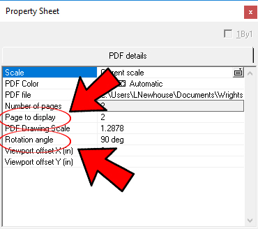
1) If your PDF is on the wrong page, right click and change the floor to 1.
2) If the PDF is turned so you cannot easily read it, then right click again and change the Rotation Angle to 90 degrees (in this case) or whatever you need to make it right side up.
3) Change Grid Settings to 1”x1” by clicking on the Drawing tab at the top, and then in the dropdown list will be a “Grid Settings”. They were probably on 12”x12” and you will switch the setting back to 12”x12” later. (No image available.)

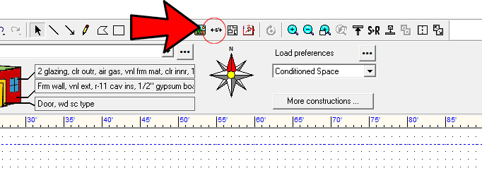
4) Click on your Dimension Tool. (It’s located just left of the CAD and PDF tools.)
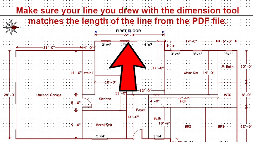
5) Draw one side of a long room. In this example, a 22 ft. long great room. (Do not pick a short 6 ft. bathroom wall.)
6) Let’s say it turns out to be 17.83’. A box will come up that will allow you to change the 17.83 to 22.00 in this example. After it has been scaled – line up the two lines to make sure they look to be the same length.
7) Place the corner of your PDF structure on one of your grid points.
8) Change grid points back from 1” x 1” – back to 12”x12”.
Want to watch a short video on this subject. Click here.